Play Ball with SVG and XSLT
Abstract
The Scalable Vector Graphics (SVG) graphic Extensible Markup Language (XML) format is highly capable of describing complex images in a single SVG file. The author encountered a real-world requirement to align multiple SVG images with precise spatial relationships. Multiple output XML files are used to create physical objects that, themselves, had to be aligned precisely. Addressing this challenge reduced the number of source SVG files to one. An automated process readily and reliably produces the many required multiple output SVG files. The author divined and imposed simple declarative techniques on top of existing constructs in the Inkscape SVG authoring tool. Extensible Stylesheet Language Transformations (XSLT) stylesheets were developed to interpret these declarative constructs. This interpretation massages the single design SVG XML file to create the required dozens of individual review and production SVG XML files. These declarative techniques were written for one project and then proven using a second project. The tools implementing these techniques are freely available on GitHub.
Table of contents
Introduction
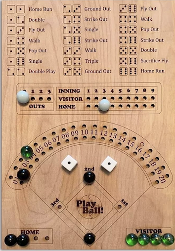
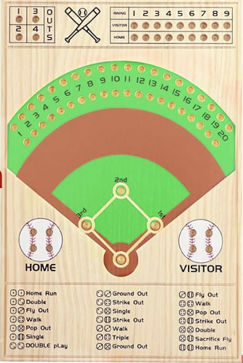
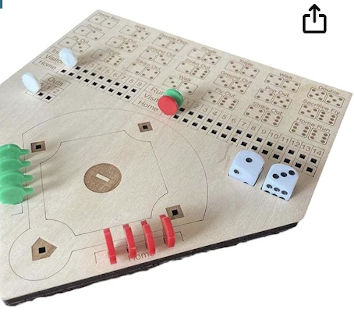
One day my son approached me for assistance in teaching my young grandchildren the rules of Major League Baseball. I looked on the Internet for games to play, and found a number of very simple dice-and-marble games that followed basic principles of baseball play but could not be used for teaching rules in detail. They might be appropriate at the very beginning, but soon would not have the fidelity needed to learn about what they see on television or might play in little league. Moreover, the games do not incorporate some of the rule changes recently introduced by MLB. Interestingly, the different boards all use the same dice combinations and all are only in English!
 |
 |
 |
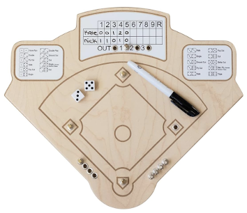 |
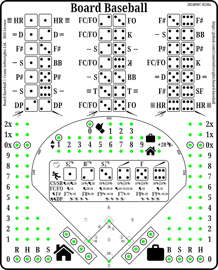
I want to teach my grandchildren about pitching, counts, and base stealing, none of which is covered in the games I found. So I created a new game with a second perspective, specifically that from the pitcher.
And I want the playing surface to teach the abbreviations found in box scores. By using MLB abbreviations instead of using English, the game becomes universal and language independent. I hope this helps the children learn to read scorecards and box score summaries. And I think it may interest players who don't speak English as a first language.
It came to mind that I could create a playing board of my own with the fidelity I need to teach the rules beyond the basics offered by other games. Moreover, I could create multiple versions of the playing surface to meet the needs of the people who want to play my version of a board game.
Scalable Vector Graphics (SVG) is an Extensible Markup Language (XML) vocabulary of the semantics of drawn figures and diagrams. A print version of my game concept could be created with a single SVG file. After being printed, dress pins can be used for play when there is foam placed behind the paper:
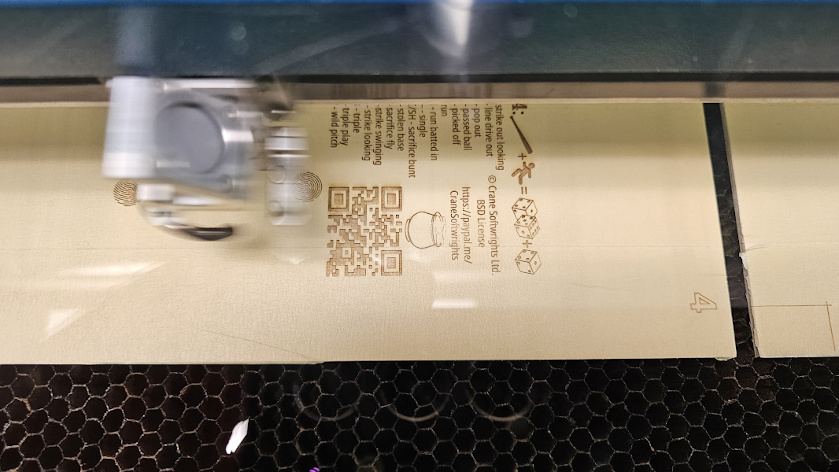
My son introduced me to our local Ottawa Public Library’s free use of a commercial-grade laser cutting machine. The machine both cuts through material and burns the surface of material based on the content of a single SVG file. A line of width .001in (inch) cuts the material. All other non-white content is shallow-burned as a raster image.
First, the raster burns the surface, the mirror of the laser zipping across at up to 1m per second with a resolution of 600dpi (dots per inch) with low power leaving behind a little smoke and a debossed image of all non-white (a 5-second video):
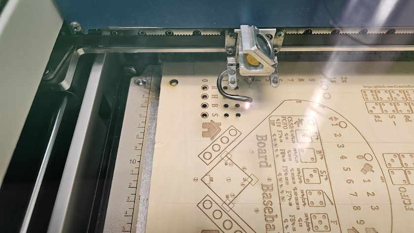
Then, with the material remaining untouched on the stationary flatbed, the laser cuts all .001in lines in the SVG tracing them slowly with high power and a lot of smoke (a 5-second video):
A double-sided single-board is created with two SVG files. The first file prepares the front of the board and cuts all of the holes. The back of the board doesn’t need any holes, just a raster image. Not a lot of coordination is needed between the two SVG files for this to work:
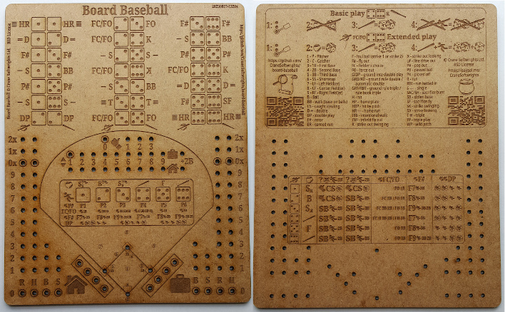
The challenge
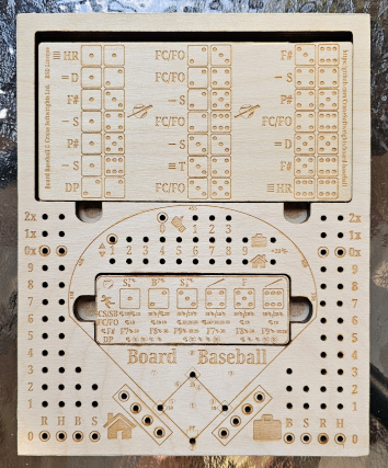
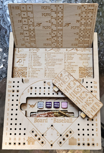
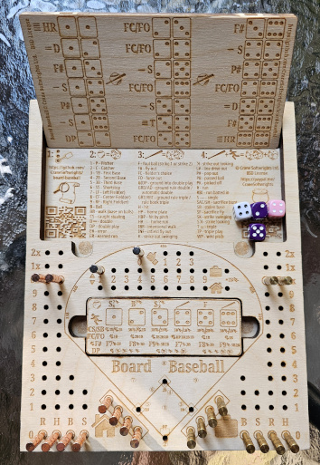
A more elaborate game board setup involves gluing together six levels of wood providing cavities for the storage of game pieces:
 |
 |
 |
But that requires coordination and precise placement of cuts and holes over multiple levels at the same time. This needs to ensure precision placement in six separate SVG files of:
76 small peg holes,
12 medium-sized rare-earth magnet holes,
4 dice cradles,
3-level storage compartment lid over a 4-level cavity,
3-level 2-sided dice play panel, and
six alignment holes (two for the compartment lid, two for the panels, and two at the corners of the boards, flipped for the back).
Consider the challenging need to produce six separate SVG files to cut six pieces of wood to be bonded together to form the cavities and the deep peg holes. These are the six individually-cut boards that make the 3-dimensional game version with cavities shown in the previous photograph:
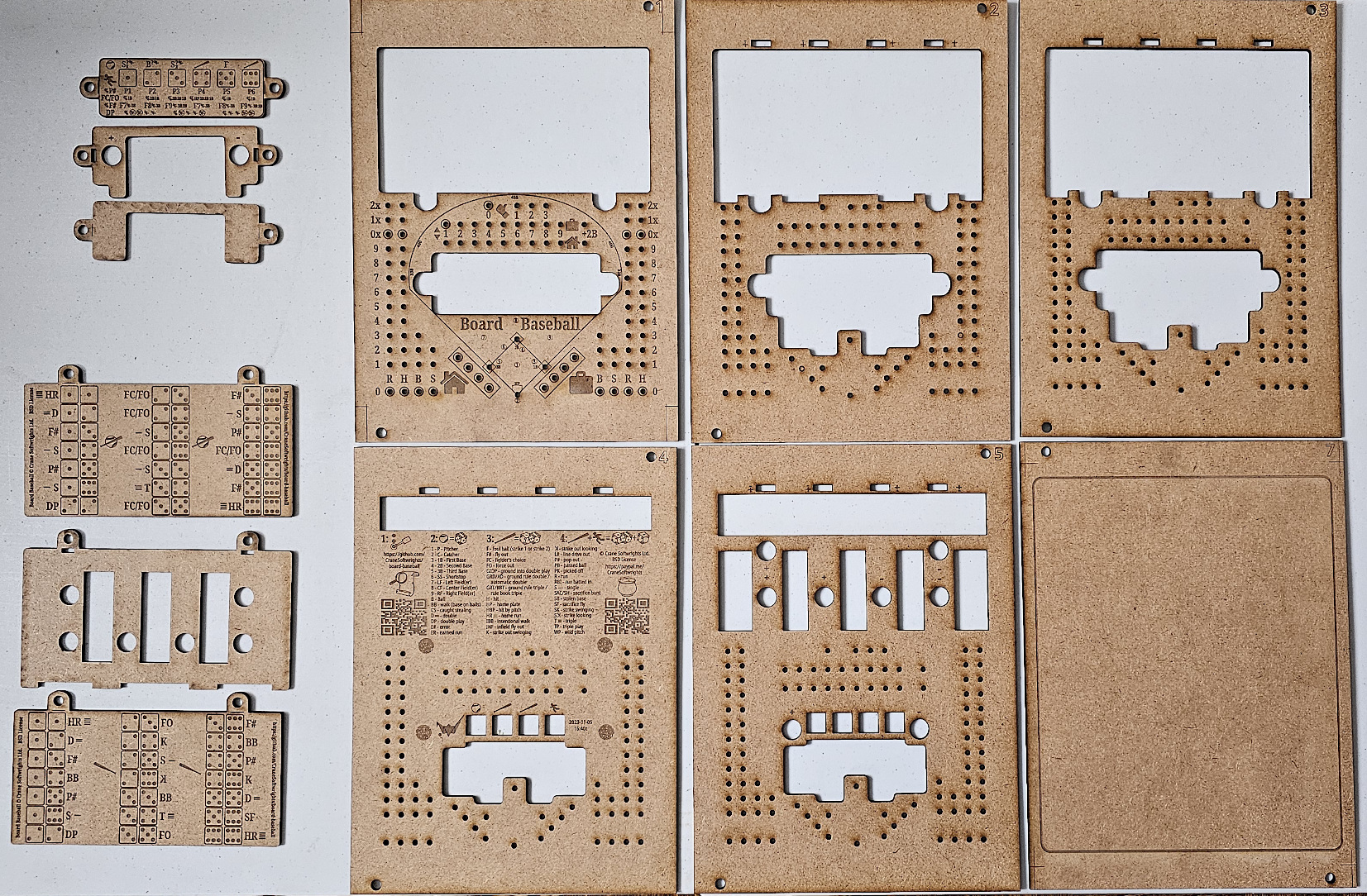
These six SVG files need to be very carefully coordinated so that the cuts are precisely aligned on every level:
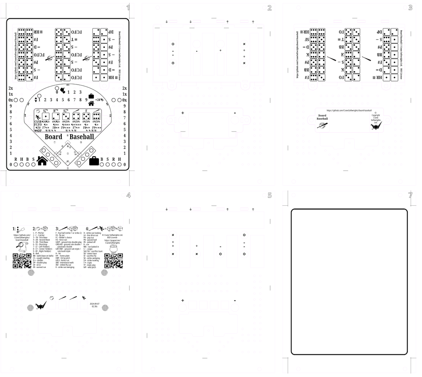
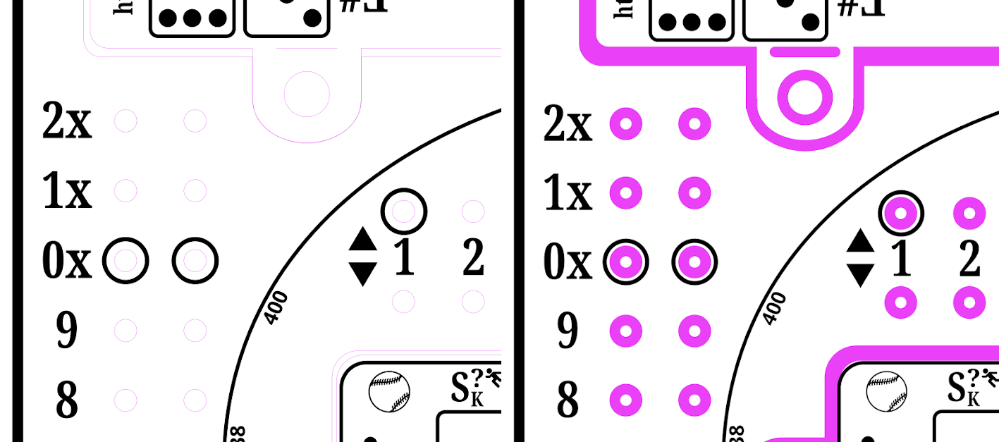
The .001in lines needed in the SVG are practically invisible, even when using a bright magenta colour to distinguish these lines from design lines. Moreover, the resulting laser cut is almost 1mm in thickness. The challenge here is to know during the design time the effective cutting width and not the specified cutting width. Accordingly, the design process has to accommodate what actually will be produced by the cutting laser. This is illustrated on the right with the magenta lines being 1mm thick instead of .001in thick in the design SVG. But the cutting process still needs .001in thick lines in the burn SVG to function.
The manual process
To successfully distill the semantics for a system requires understanding how that system already is working. In this case, the "system" is the successful manual creation of multiple burn PDF files from a single coordinated design SVG file.
Using a single design SVG file promotes the alignment of all of the cut edges. By breaking all of the needed pieces into separate groups and layers, these can be shared across the different board levels. The levels are then assembled into the finalized burn SVG files that are published into the burn PDF files and review PNG files.
Manually, I went through the pattern of making only those layers for a given level visible, changing the stroke size to accommodate the burn, and writing out the file that is needed. The process was labourious and error prone. Ofttimes I would miss steps. I was unable to review the completed work meaningfully before committing the burn files to costly physical materials.
I then parcelled shared portions of cuts and rasters into separate layers to be combined. In this image I have exposed one of the burns from each of four levels, two through five, in order to review the interaction between the levels:
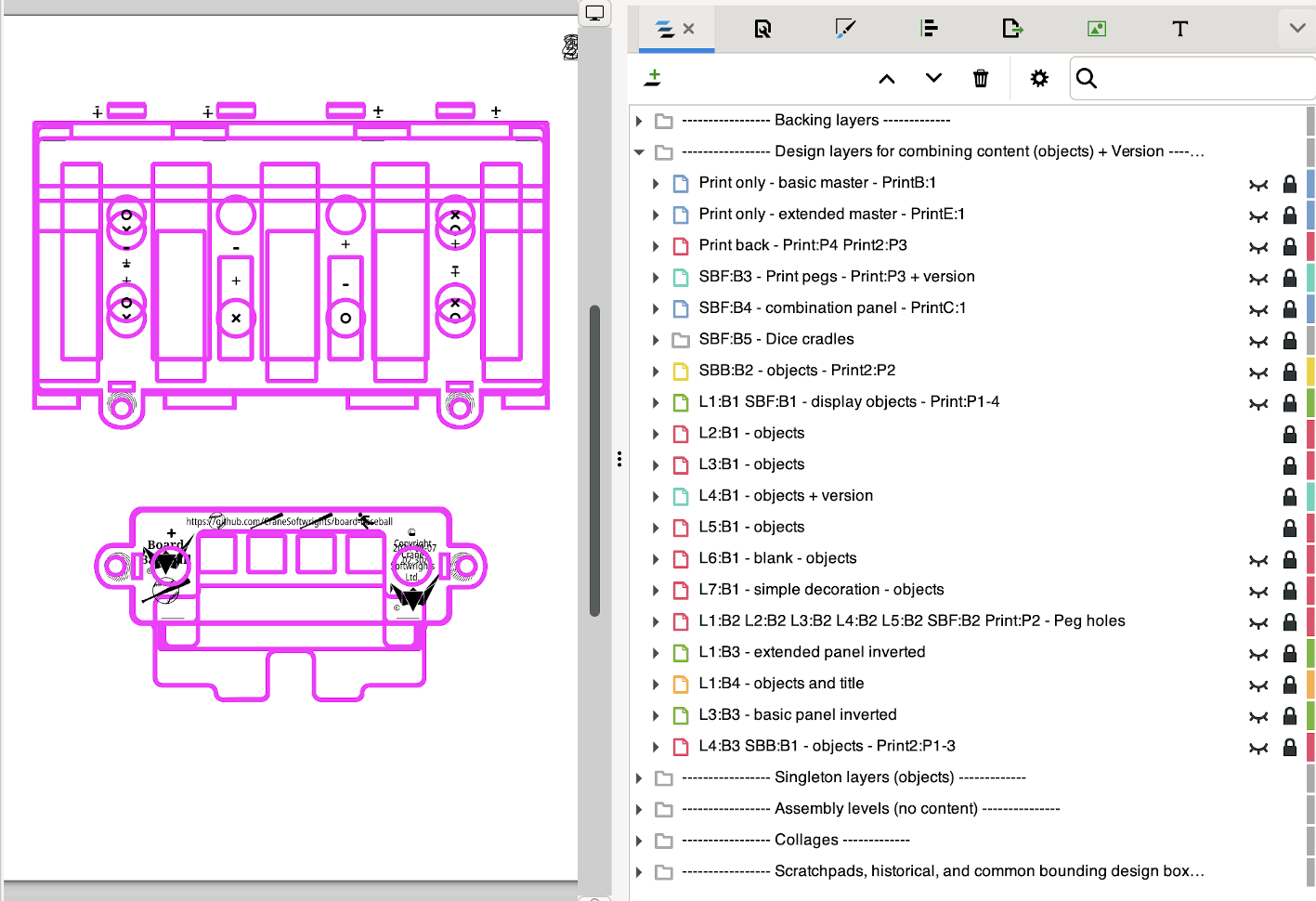
To identify layers and groups to be used in levels, the titles of layers that are to be referenced have a syntax: a referential name token followed by a colon, optionally followed by a name token of arbitrary meaning useful for organization. When I write “L3:B1”, I read “level 3 burn 1”. There are no restrictions on the name token following the token, as there may be many ways to visualize and manage all of the burns used in a single level. All of the “L3:*” layers and groups are included in the creation of level “L3”. Of interest, note how many of the level burns include the 76 peg holes.
To manually assemble multiple groups and layers into a level combination assembly, one must selectively make the groups and layers visible with all other layers invisible. Here I have manually made all the level 3 layers and groups visible:
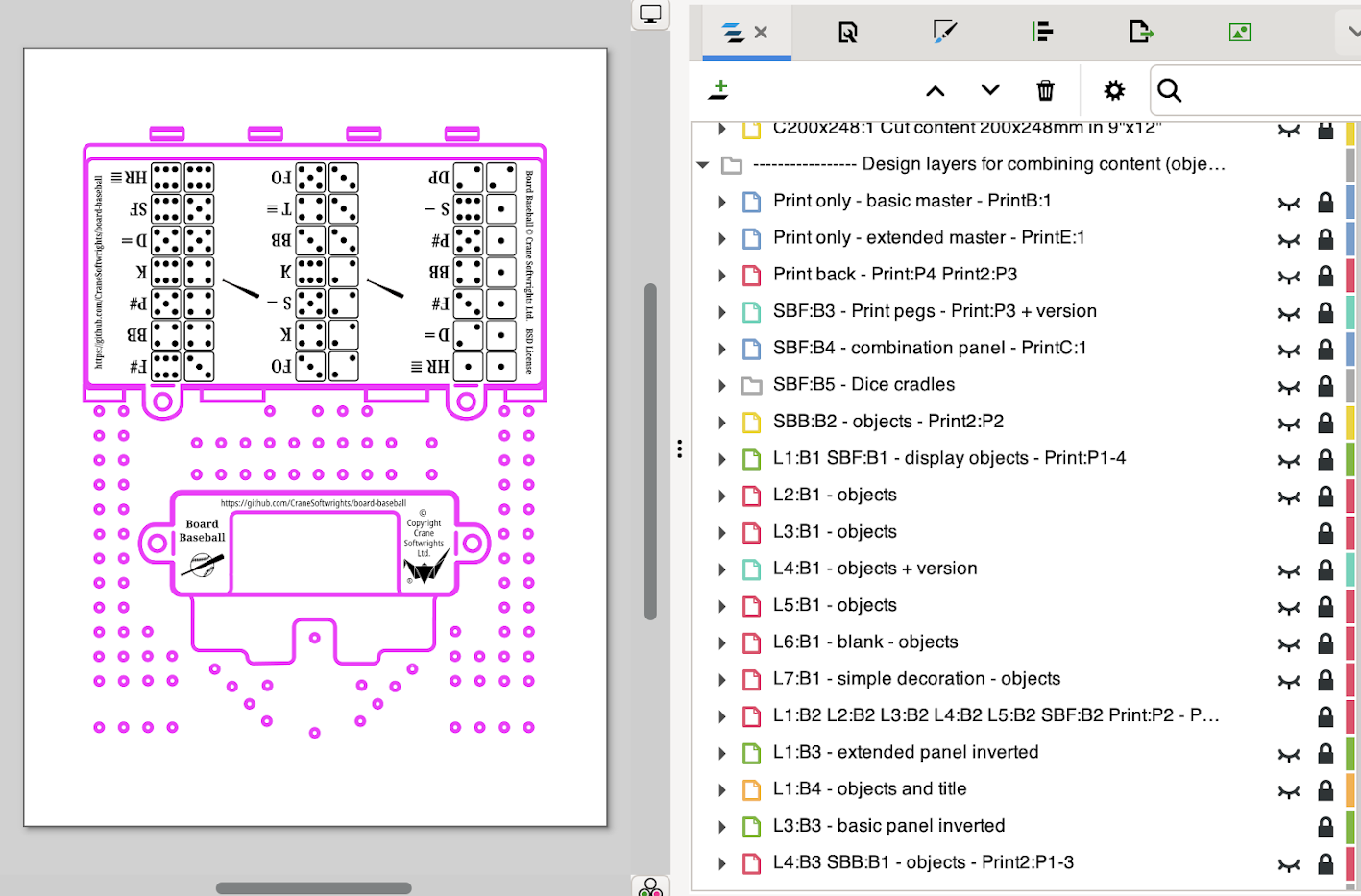
Leveraging layer labels using a declarative scheme
But I recognized the pattern I was following and I could see a declarative approach. I identified the steps of the pattern and documented the semantics of what I was doing in each step. I then came up with declarative labels for each semantic operation, and a declarative labeling scheme for the semantic operands.
Because SVG is expressed in XML, Extensible Stylesheet Language Transformations (XSLT) can be used to read and write SVG files. The XSLT <xsl:result-document> facility supports writing multiple output XML files from a single input XML file. Using this, the many SVG burn files can be produced separately for print production, single-board production, double-board production, and six-board production (with two different backing rasters), all from a single design SVG file with multiple SVG layers and groups. Interpreting the burn SVG files into burn PDF files also can be automated by invoking Inkscape with scripts.
I then associated a declarative syntax to trigger the semantic operators on semantic operands when used in the Inkscape titles of each SVG layer or group:
identify layers and groups to be used in levels
all tokens in the title that contain a colon identify the assemblies in which the layer or group is used
the left portion before the colon identifies the level the layer or group belongs in
the right portion after the colon is arbitrary and ignored, useful only for management and conceptualization
assemble multiple level groups and layers into a level combination assembly
the second token includes an equal sign “=”
the first token identifies the target assembly
the remaining tokens specify the identity of source layers and other assemblies to be assembled
perform post-assemble tasks on the resulting level assemblies
the equal sign “=” in the second token is augmented with action directives, such as
crop the image removing outside white space (useful for printing)
rotate the resulting image (to accommodate the geometry of flatbeds in the laser cutters)
combine and position the completed assemblies in a collage (for large laser cutter flatbeds to produce two, four, or six boards in a single run)
manage the output process to organize the generated levels in different subdirectories (there are 39 output SVG files for numerous print and physical board productions, and having them all end up in a single directory is inconvenient)
the first token ends in an oblique “/” naming the subdirectory
all of the assemblies in layers inside this layer
the content of the title following the first token is written into a README.txt in the subdirectory
To declaratively assemble multiple level groups and layers into a level combination assembly, empty layers have a title where the second name token includes the equal sign “=” as an assignment operator. The first name token identifies the assembly which produces the actual burn files used in the physical world. The remaining name tokens specify which levels (and, implicitly all of the layers and groups identified by the level) are included in the burn. Note that complete assemblies also can be included in other complete assemblies.
In this image, you can see the SVG groups used to group the burn file targets in different subdirectories:
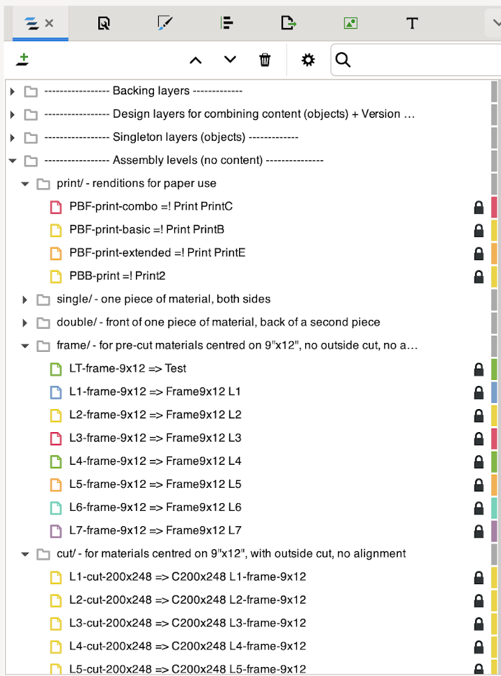
The text that follows the “/” in the directory groups is copied into a README.txt file in the directory.
The assignment operators and action directives defined so far are (more are being considered):
‘=’ - simple assembly without post processing
‘=!’ - clip the results to the printable content
‘=>’ - rotate the resulting image 90 degrees clockwise
‘=<’ - rotate the resulting image 90 degrees counterclockwise
‘=#’ - assemble multiple assemblies into a collage of non-overlapping images
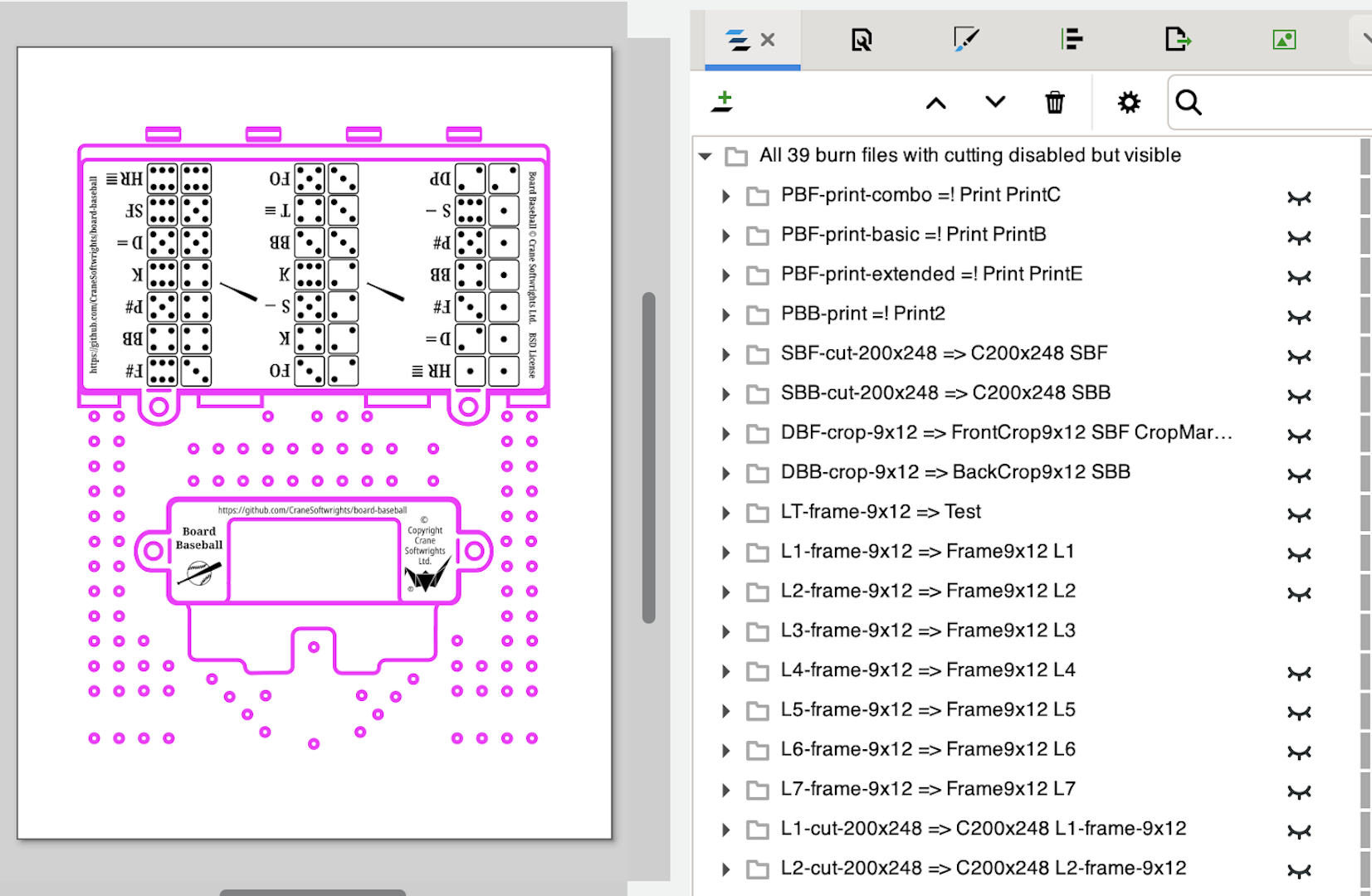
Finally, as a designer, I need to have confidence that the resulting assemblies are going to work before I spend my money consuming materials. I don’t want to have to throw away costly burns I cannot use. For review purposes the XSLT creates a very large single SVG file with every SVG completed assembly as a child group that is hidden from view. I then can selectively expose any one completed level to review that the assembly produced what I expected. Moreover, I can expose more than one complete level at a time to review the alignment between levels. I also echo the assembly instruction in the group title so that I can review the directives in light of what I see on the canvas.
In this image I am reviewing the completed level “L3-frame-9x12” by making it visible:
The XSLT interprets the semantics represented by the syntax and creates the individual SVG to be used for the actual burn PDF file “L3-frame-9x12.pdf” for assembly “L3-frame-9x12” sent to the laser cutter. This SVG has been adjusted such that the magenta lines to be the cut now have the required specified width (.001in), not the review effective width (1mm):
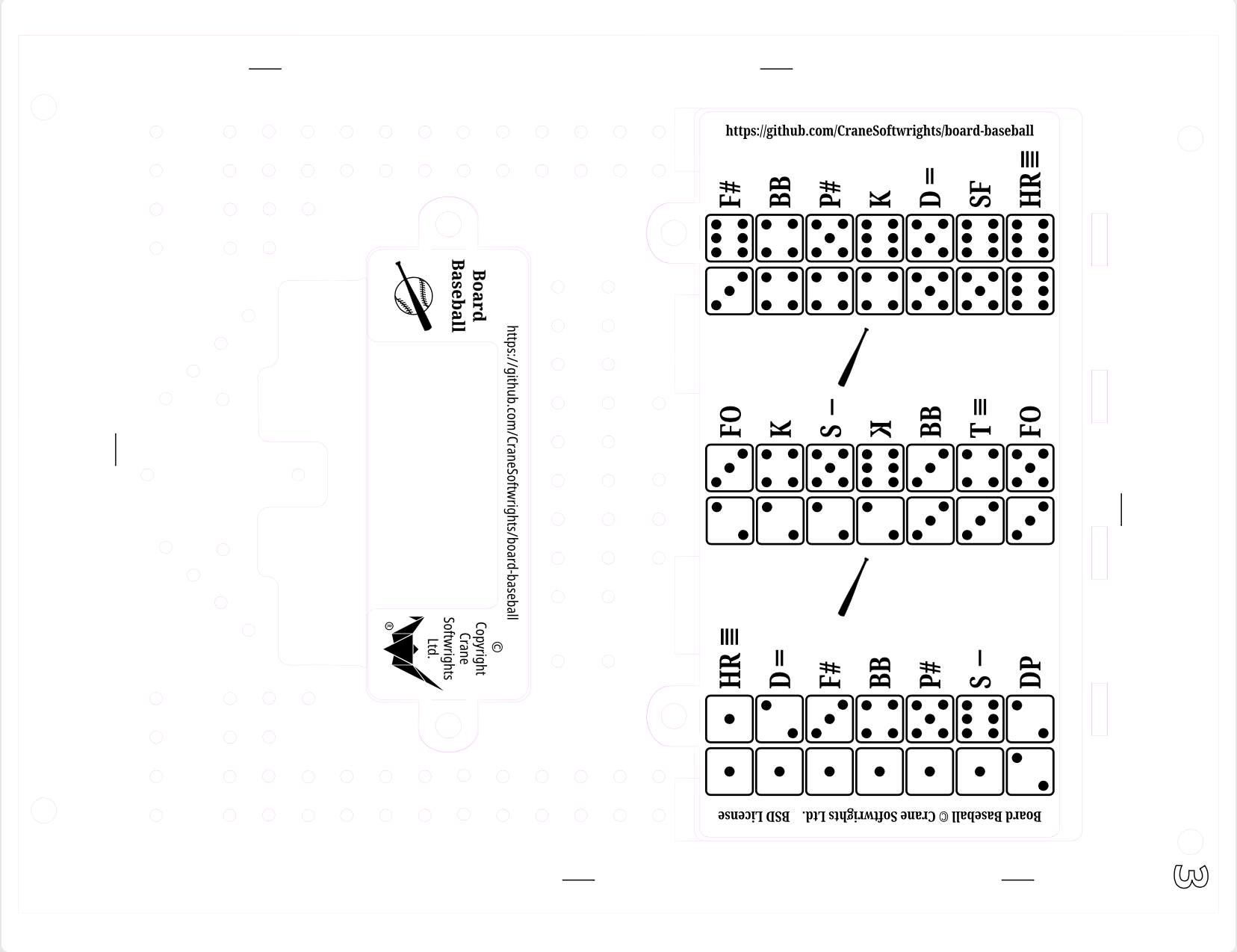
Inkscape is then invoked to convert the SVG to PDF by processing “L3-frame-9x12.svg” into “L3-frame-9x12.pdf” while applying any post-processing scripting specified by the assembly assignment operator details.
Scripting
Post-processing with Inkscape actions
Inkscape offers the feature to script its behaviours using “actions”. To see a list of available actions, use this command line invocation:
inkscape --action-list
To apply a script of actions to an input file, use this command line invocation:
inkscape --actions-file=scriptname svgfilename
Canned scripting - Collages
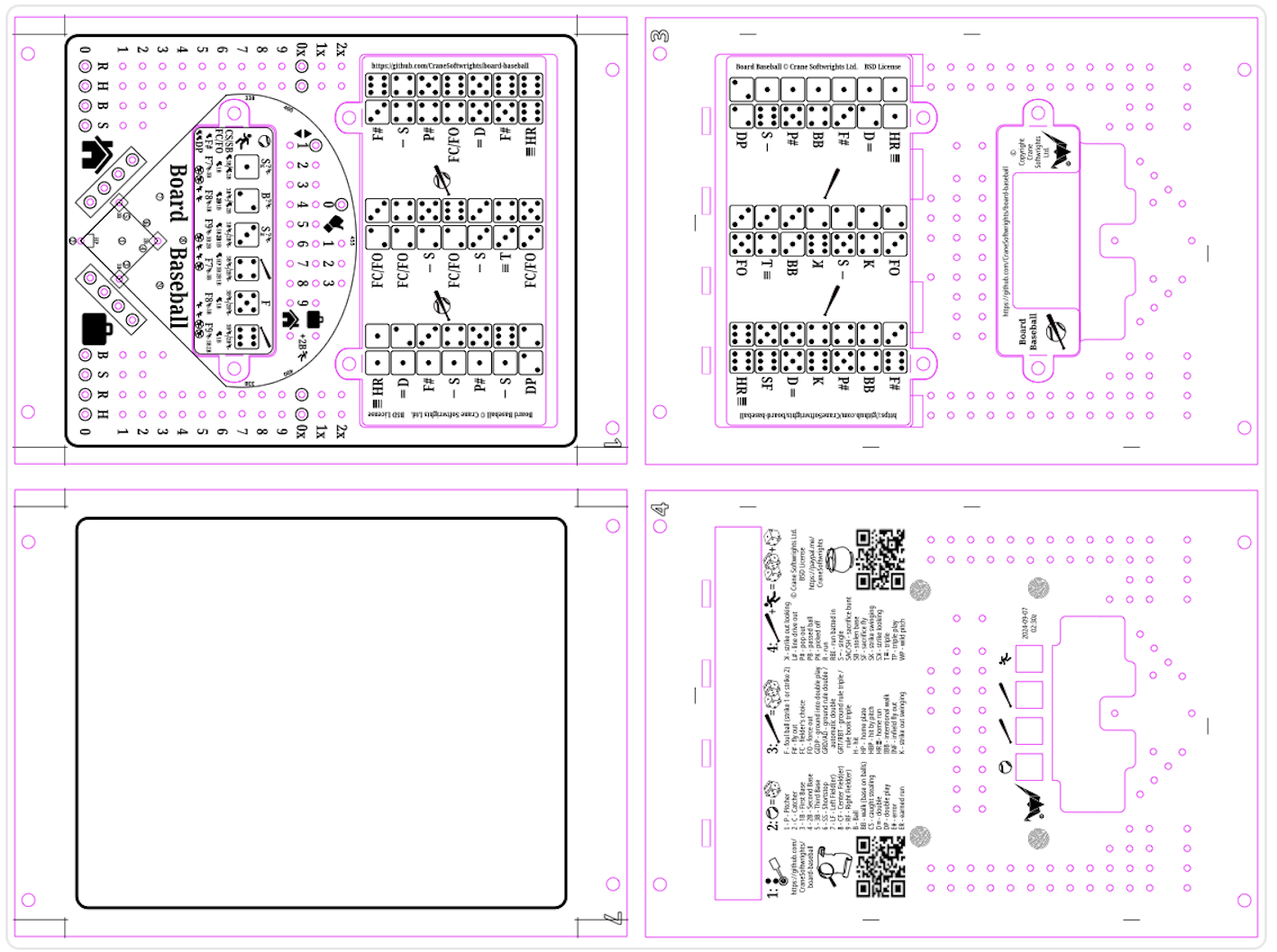
Many cutting machines have large beds on which to place larger pieces of material. To take advantage of these, I create collages of boards using Inkscape action scripts I’ve written. At my library there is a cutter that accepts 24”x18” material. I can fit four 12”x9” boards in a single burn. In this example the 2x2 collage is named “1374-18x24-collage-board-baseball-crane” which lays out boards 1, 3, 7, and 4 to fit:
This is the 2x1 collage named “25-9x24-collage-board-baseball-crane” for the two middle layers, 2 and 5, that have no exposed surfaces to the game players:
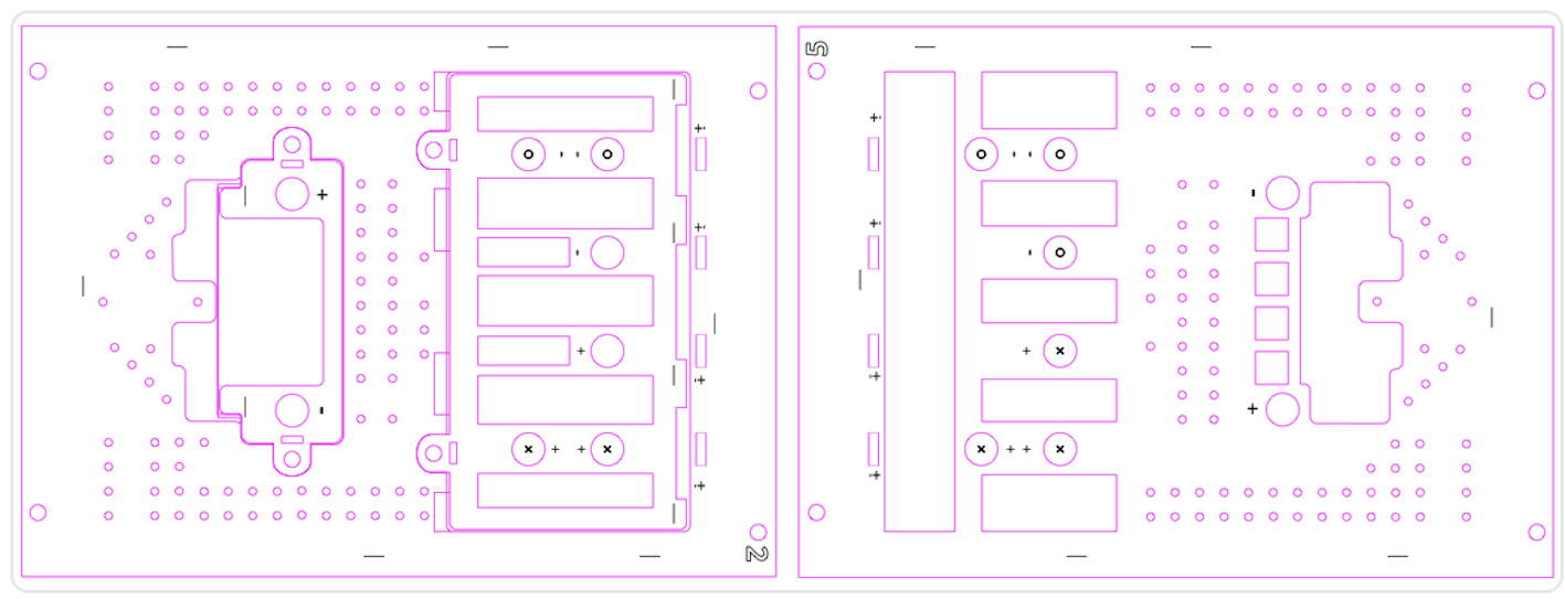
Using these I can burn a complete game with two burn/cut steps in a larger machine rather than six burn/cut steps in a smaller machine.
Custom scripting
I am exploring the implementation of arbitrary custom scripting where a text object contains the Inkscape script contents and the assignment operator identifies the title of the text object.
A second project
I then created a second peg game, this time using playing cards instead of dice. It is a pursuit game and was very much embraced by our 5-year-old and 7-year-old grandchildren. It is an amalgam of different pursuit games. According to ChatGPT the game is unique but similar in concepts to Sorry!, Tock, Headache, Parcheesi, Ludo, Aggravation, Frustration, Trouble, Pachisi, Mensch ärgere Dich nicht, Sorry! Sliders, Chaupar, Super Tock 6, Uckers, Royal Game of Ur, Pegs and Jokers, Parqués, Petits Chevaux, Kimble, Kraków, The Game of Goose (I stopped at 21 ... there are more!).
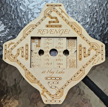
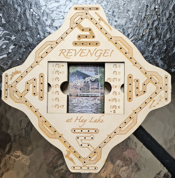
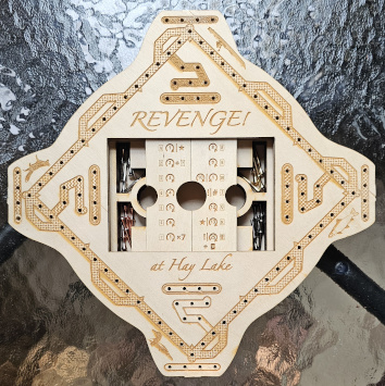
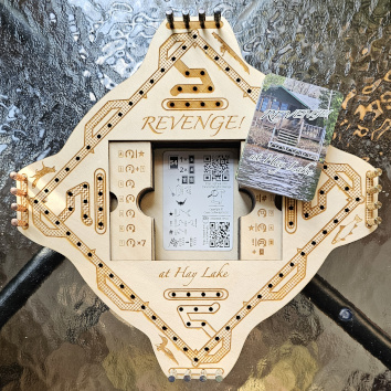
Coincidentally while creating this game, we were renting a cottage at Hay Lake, a three-hour drive west of our home in Ottawa, Canada. I made our stay at Hay Lake the theme of the board and the playing cards. The name of the game is “Revenge at Hay Lake”.
Again, different burn SVG layers were designed in a single design SVG file. This created cavities and door slides to store pegs and cards, and coordinated multi-layer holes for the cribbage pegs.
 |
 |
 |
 |
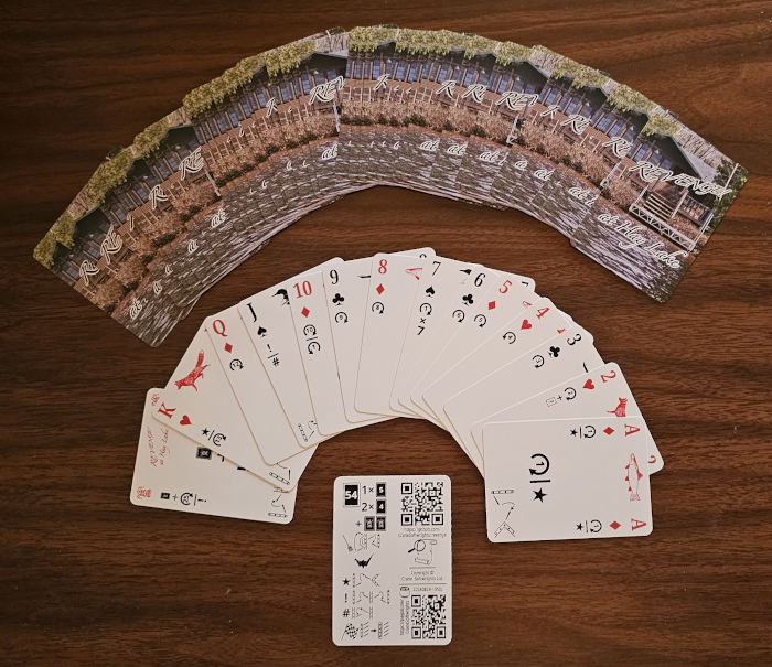
Groups and layers were re-used to create a complete deck of 55 playing cards (52 deck cards, 2 jokers, one instruction card) that I had professionally produced:
Two tools
convertBadStrokes4designSVG.xsl
Sometimes an image imported from a free SVG clip art library contains strokes around .001in and end up cutting the final work instead of burning.
Sometimes a shape created with a safe stroke width is transformed and massaged through the design process to shrink the safe stroke width to an unsafe stroke width.
This tool converts unexpected or unintended cutting strokes to a minimum non-cutting stroke width of .003in .
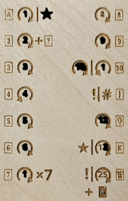
In this image the play numbers and star all were created at higher resolution with a safe stroke width greater than .002in to be safe. I shrank the components to fit in a smaller area of the board. Unbeknownst to me, the effective stroke width ended up being .001in. When I put the material in the laser machine, the cut process ended up cutting out the numbers rather than leaving them alone as a raster. Thankfully, this was my first burn of the day and so I knew not to create any other burns until I addressed the problem. Unfortunately, I had to throw out the material as useless, and it meant that I lost the use of a valuable time reservation slot for the busy resource used by many in the community. And these slots are limited in number to each patron each month.
designSVG2burnFiles.xsl
This tool does the heavy lifting of creating the many burn SVG files from the one design SVG file, based on the declarative syntax encoded in the group and layer titles.
It creates the large SVG review file used to check the results of the declarative assemble directives.
It creates the individual SVG burn files with the content needed for every burn action in the laser cutters. This is the step that converts every magenta-coloured stroke, regardless of the stroke width, to have a width of .001in. The colour used is configurable and does not have to be magenta.
It creates the individual Inkscape action scripts that manipulate each SVG file according to post-processing directives (if present for that file) and directs Inkscape to make from each the resulting processed SVG files, PNG preview files, and PDF cutter burn files.
Finally, it creates an invocation shell script that, for each burn SVG file, opens the file in Inkscape with its associated action script file to produce all of the output files.
GitHub actions
GitHub is a hosting service for git repositories. Git is a data management and revision control system. It offers scripting to perform operations on GitHub's server rather than on one's own personal computing environment. Both of these game projects are hosted as public GitHub repositories, as well as the two XSLT tools used to develop and produce results.
The YAML scripting triggered by a push to a repository produces all the ready-to-use result SVG and burn files for a given design SVG file by:
installing the required fonts - Noto Sans and Noto Serif,
installing the required tools - Inkscape and SaxonHE,
installing the designSVG2burnFiles.xsl stylesheet and its dependencies, from Crane’s git repository
invoking the XSLT stylesheet to create the large review SVG file and the many burn SVG files
invoking the synthesized shell script to build all of the resulting print and burn files with Inkscape
updating the git repository with the latest PNG preview files
packaging the results for download from the actions menu
creating a git release package and posting it to the repository for download by the public (for the shared develop, qa, and main branches only, not for other user-specific branches),
Conclusion
Divining, imposing, and interpreting a novel declarative scheme on top of existing constructs in Inkscape gave me the ability to specify necessary actions and results without having to perform the labourious and error-prone steps manually. Moreover, it promoted a powerful streamlined design environment for authoring multiple SVG files in a tool written to create a single SVG file. I mimicked the labourious manual system by identifying semantic operations and operands to be implemented by XSLT stylesheets. I expressed these operations and operands in a declarative syntax in existing Inkscape title constructs. This automation of numerous finicky production steps saved a tremendous amount of time and gave me the confidence that the real-world results would be correct. Also, this saved me money by reducing the waste of creating bad burns.
Download
Everything is freely downloadable at these clickable short links that take one to GitHub:


